


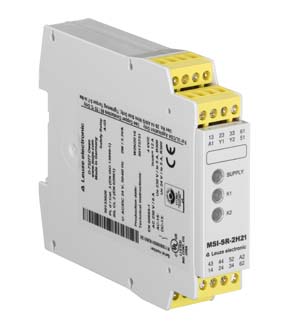


MSI-SR-2H21-01
Safety relay
Part no.:
50133016
| Series | MSI-SR-2H21 |
| Application | Evaluation unit for two-hand control devices in accordance with DIN EN ISO 13851 type IIIC |
| Functions | For stop category 0 Monitoring of the synchronous actuation Two-channel actuation (one normally open contact and one normally closed contact for each) |
| Restart | Through synchronous actuation |
| SIL | 3, IEC 61508 |
| SILCL | 3, IEC/EN 62061 |
| Performance Level (PL) | e, EN ISO 13849-1 |
| PFHD | 3E-08 per hour |
| Mission time | 20 years, EN ISO 13849-1 |
| Category | 4, EN ISO 13849-1 |
| Continuous current per current path, max. | 6 A |
| Supply voltage UB | 24 V, AC/DC, -15 ... 10 % |
| Power consumption, max. | 1.9 W, For 24 V, plus output load |
| Nominal voltage UN | 24 V |
| Nominal frequency | 50 ... 60 Hz |
| Rated control supply voltage US at AC 60 Hz | 20.4 V |
| Rated control supply voltage US at AC 50 Hz | 26.4 V |
| Max. rated control supply voltage at AC 50 Hz | 26.4 V |
| Min. rated control supply voltage US at AC 50 Hz | 20.4 V |
| Min. rated control supply voltage US at DC | 20.4 V |
| Max. rated control supply voltage at DC | 26.4 V |
| Min. rated control supply voltage at DC | 20.4 V |
| Rated power DC | 2.4 W |
| Galvanic isolation between supply and control circuit | Yes (when UN ≥ AC 115-230 V, AC 230 V) |
| Number of outputs, safety-oriented, non-delayed, contact-based | 2 Piece(s) |
| Number of outputs, safety-oriented, delayed, contact-based | 0 Piece(s) |
| Number of outputs, signaling function, non-delayed, contact-based | 1 Piece(s) |
| Release current paths | NO |
| Signaling current paths | NC |
| Contact material | Ag alloy, gold-plated |
| Usage category AC-15 (NO contact) | Ue 230V, Ie 3A |
| Usage category DC-13 (NO contact) | Ue 24V, Ie 2,5A |
| Short circuit protection (NO contact) | gG class safety fuse 6A, melting integral |
| Nominal switching voltage, release current paths AC | 230 V |
| Max. thermal continuous current Ith, release current paths | 6 A |
| Max. thermal continuous current Ith, signaling current paths | 2 A |
| Max. total current I² of all current paths | 9 A² |
| Mechanical life time | 100,000,000 switching cycles |
| Executing the switching function of the inputs | Changeover |
| Nominal output voltage DC | 24 V |
| Input current at the control inputs (safety circuit/reset circuit) | 60 mA |
| Max. peak current at the control inputs (safety circuit/reset circuit) | 1,000 mA |
| Max. cable resistance, per channel | ≤ (5 + (1.333 x UB / UN - 1) x 200) Ω |
| Response time (automatic start tA2) | 40 ms |
| Response time (manual start tA1) | 40 ms |
| Release time tR | 50 ms |
| Synchronous time monitoring tS | 500 ms |
| Recovery time tW | 250 ms |
| Regression delay | 50 ms |
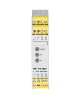
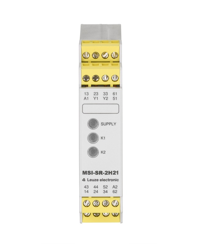
| Number of connections | 1 Piece(s) |
| Function | Signal IN Signal OUT Voltage supply |
| Type of connection | Terminal |
| Type of terminal | Screw terminal |
| No. of pins | 16 -pin |
| Connection cross sections | 1 x 0.2 to 2.5 mm², wire 1 x 0.25 to 2.5 mm², wire with wire-end sleeve 2 x 0.2 to 1.0 mm², wire 2 x 0.25 to 1.0 mm², wire with wire-end sleeve |
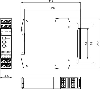
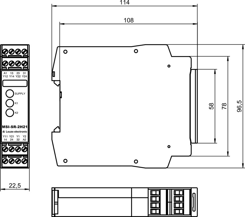
| Dimension (W x H x L) | 22.5 mm x 96.5 mm x 114 mm |
| Net weight | 200 g |
| Housing color | Gray |
| Type of fastening | Snap-on mounting |
| Ambient temperature, operation | -25 ... 55 °C |
| Approvals | TÜV Rheinland c UL US |
| Customs tariff number | 85364900 |
| ECLASS 5.1.4 | 27371905 |
| ECLASS 8.0 | 27371821 |
| ECLASS 9.0 | 27371821 |
| ECLASS 10.0 | 27371821 |
| ECLASS 11.0 | 27371821 |
| ECLASS 12.0 | 27371821 |
| ECLASS 13.0 | 27371821 |
| ECLASS 14.0 | 27371821 |
| ECLASS 15.0 | 27371821 |
| ETIM 5.0 | EC001452 |
| ETIM 6.0 | EC001452 |
| ETIM 7.0 | EC001452 |
| ETIM 8.0 | EC001452 |
| ETIM 9.0 | EC001452 |
| ETIM 10.0 | EC001452 |
3D-CAD model - zip
EPLAN macro - edz